Schematics
This page provides a high-level overview of the electronics of the prototype. Block diagrams for each main system (battery modules, hub, and rover) are provided. Three custom PCBs were created for their function: a rover PCB, a connector PCB, and a power swap PCB. The full design files for these boards are available in KiCad and Altium file formats in the repository.
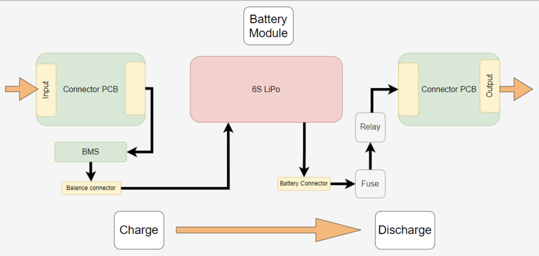
Battery Module Electronics
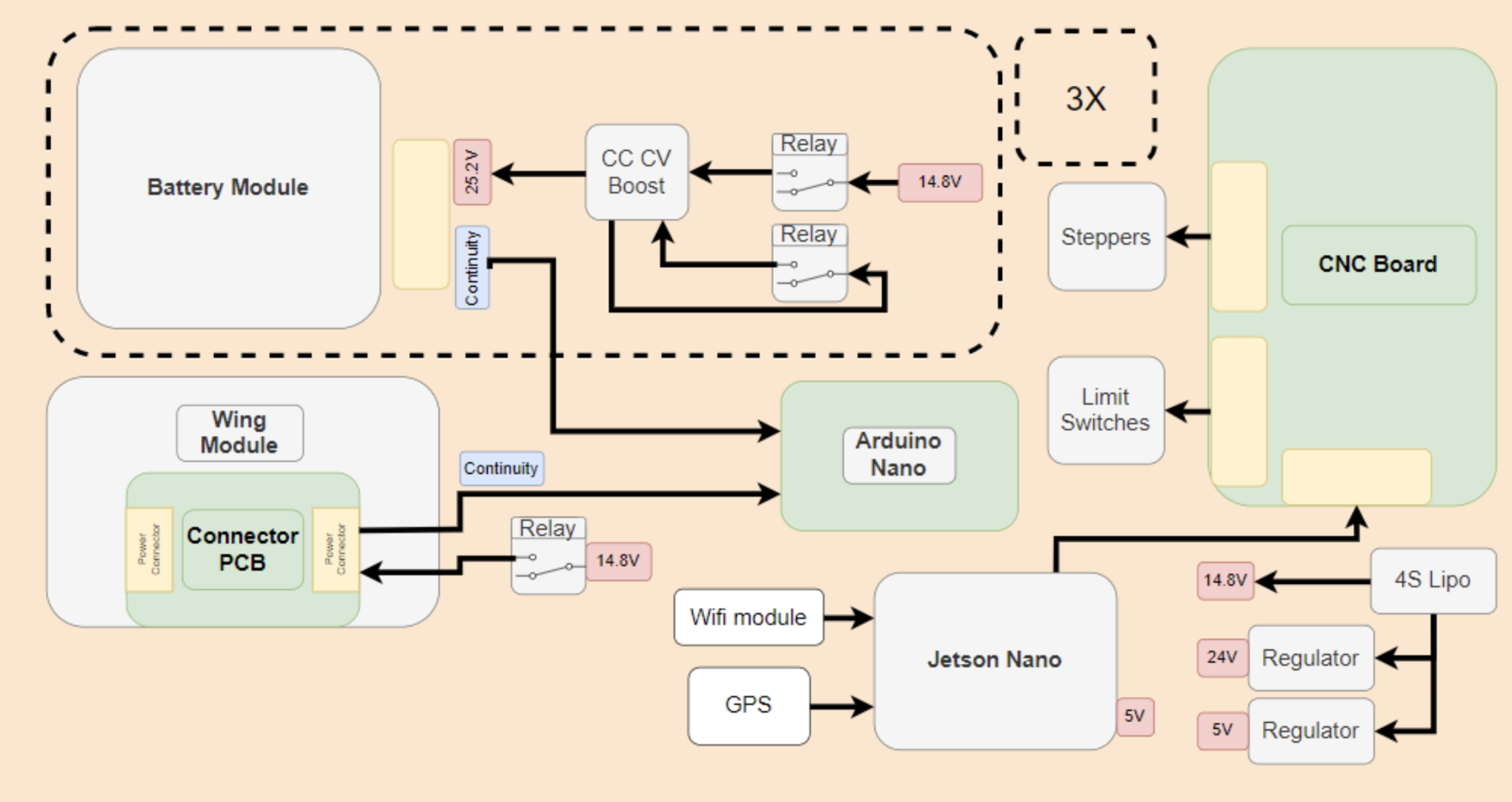
Hub Electronics
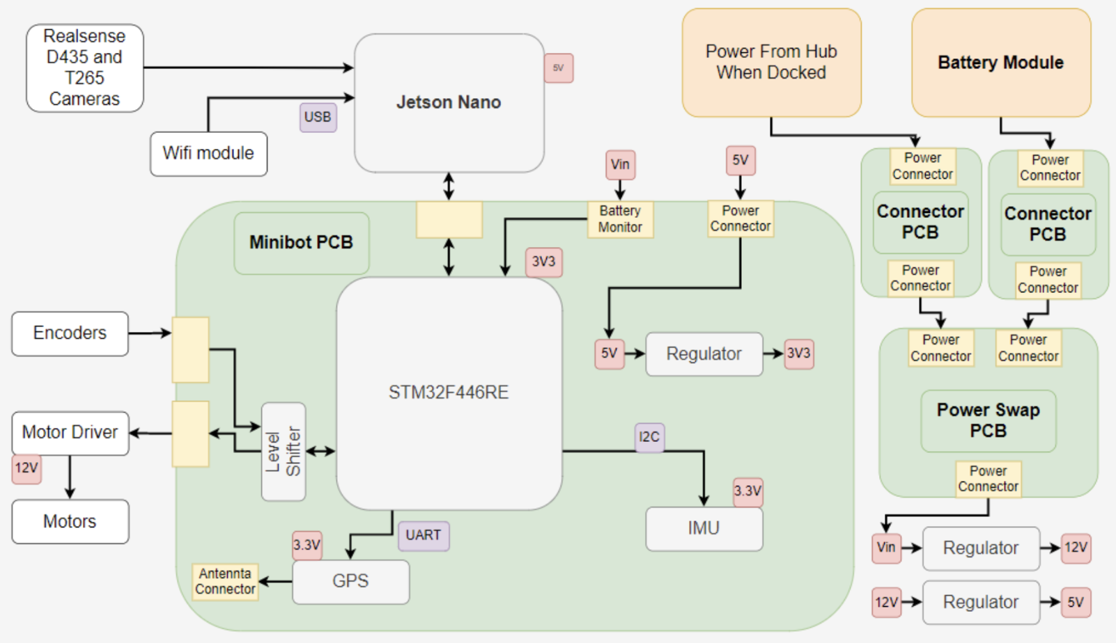
Rover Electronics